USB Thinkpad Laptop Keyboard
One thing I've wanted for a while is a USB keyboard with a trackpoint.
I made a good start with an atmega32u4 on an arduino micro board.
It exists as a product. 80USD if you're lucky, currently 300.
It also exists as a dead project. rampadc was nice enough to open source it, which was new since the last time I checked on that project. Sadly, they made some (self-admittedly) poor design choices, so we're only using the very very helpful references they provide.
The first step was finding a connector for the keyboard. It was identified as a JAE AA01B-S040VA1 on electronics.stackexchange, with some parts listed as substitutes. Chasing substitute for substitute lead to the WM6787CT-ND which looked promising, and after ordering a few, found that it does fit.
My first surface mount soldering ever:
 Beautiful, isn't it.
I lost the board files, but you can order it here.
Moving onwards to firmware to run the keyboard, I chose TMK, as it seems to be the best open-source solution.
Each of their examples comes with a few "variants", such as vusb or lufa.
V-USB is a software-only implementation of a low-speed USB device for Atmel’s AVR® microcontrollers, making it possible to build USB hardware with almost any AVR® microcontroller, not requiring any additional chip.
LUFA (Lightweight USB Framework for AVRs, formerly known as MyUSB) is my first foray into the world of USB. It is an open-source complete USB stack for the USB-enabled Atmel AVR8 and (some of the) AVR32 microcontroller series, released under the permissive MIT License (see documentation or project source for full license details). The complete line of Atmel USB AVRs and USB AVR boards are supported by the library, as are any custom user boards, via custom board hardware drivers supplied by the user.
TMK recommends using LUFA going forward, if possible.
I was told very clearly a few hours into trying to use make the USB hardware for v-usb it was a poor choice.
Explored microcontroller options, limited by what I had on on hand
- bare atmega328p
- Needs external clock, and external USB hardware. Got the external clock working, USB hardware is what was hard.
- arduino pro micro
- atmega32u4, so built in usb hardware
- not enough pins, but got the onekey TMK example running here first
- arduino micro
- atmega32u4
- has 24 pins, with a 25th if you want to solder to the tx led
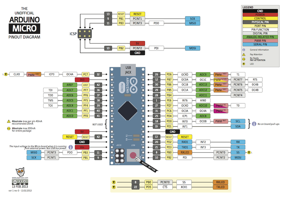 This is a useful image.
More boards and processor pinouts archived at RobotItaly which is also on archive.org.
This is a useful image.
More boards and processor pinouts archived at RobotItaly which is also on archive.org.
The person who made this(http://pighixxx.com) has a newer design. I like this design more, and I dislike their website, it's trying to be animatd, and have a fancy style, but it's just hard to use and slow to load.
avrdude -v -c avr109 -p m32u4 -P /dev/ttyACM2 -U flash:w:file.hex
-c avr109is the programmer, seems to be the one used for general "chip has USB stuff, it will deal"-p m32u4sets the device being programmed, an atmega 32u4-P /dev/ttyACM2is just the port it got on my computer-U flash whateverflashes a file to the device. You can also set or read fuses here.
It is now a keyboard that presses 'a' if you poke the right pins. I did change which pin it used, due to some unmemorable part of getting it to work.
Now, looking at the key matrix.
In the style of the TMX example I was using, I made an ascii keyboard diagram, it'll be helpful mostly later when there is more than one "layer".
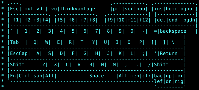
A layer is a keymap, and you can have multiple layers.
So on this keyboard, num lock would enable a different layer, see how 890 UIOP JKL; M,./ have numbers and numbers on them that match a numpad?
 The numlock turns those on instead of the "normal" keys. That is using multiple layers.
Rampadc provided the only data I could find on this matrix,
 as well as this pinout for the keyboard
 They kindly also provide the matrix in 2d array format, fairly close to what TMK expects in their github repo.
They label it as 16x8 rows/columns, and they power each row and read the column.
I use it as 8x16 pins, as it works better with the example matrix reading code from the Happy Bucking Spring Keyboard.
Having to read 8 inputs is a bit lucky, as each port is 8 pins(up to, not all pins are existing, or maybe just not exposed).
Means we can just look at PINB, which is the state of all 8 pins set to input to read the entire row.
Fun fact: AREF != 3V3, it will not power an i2c digital IO expander no matter how much you try to debug the i2c lines with an oscilloscope.
Without an expander, there are 24 pins, or 16+8, or just enough for the matrix, and nothing else, which means no trackpoint this time around.
Wire it up, write the code to scan the matrix, and pray to the dark AVR gods.
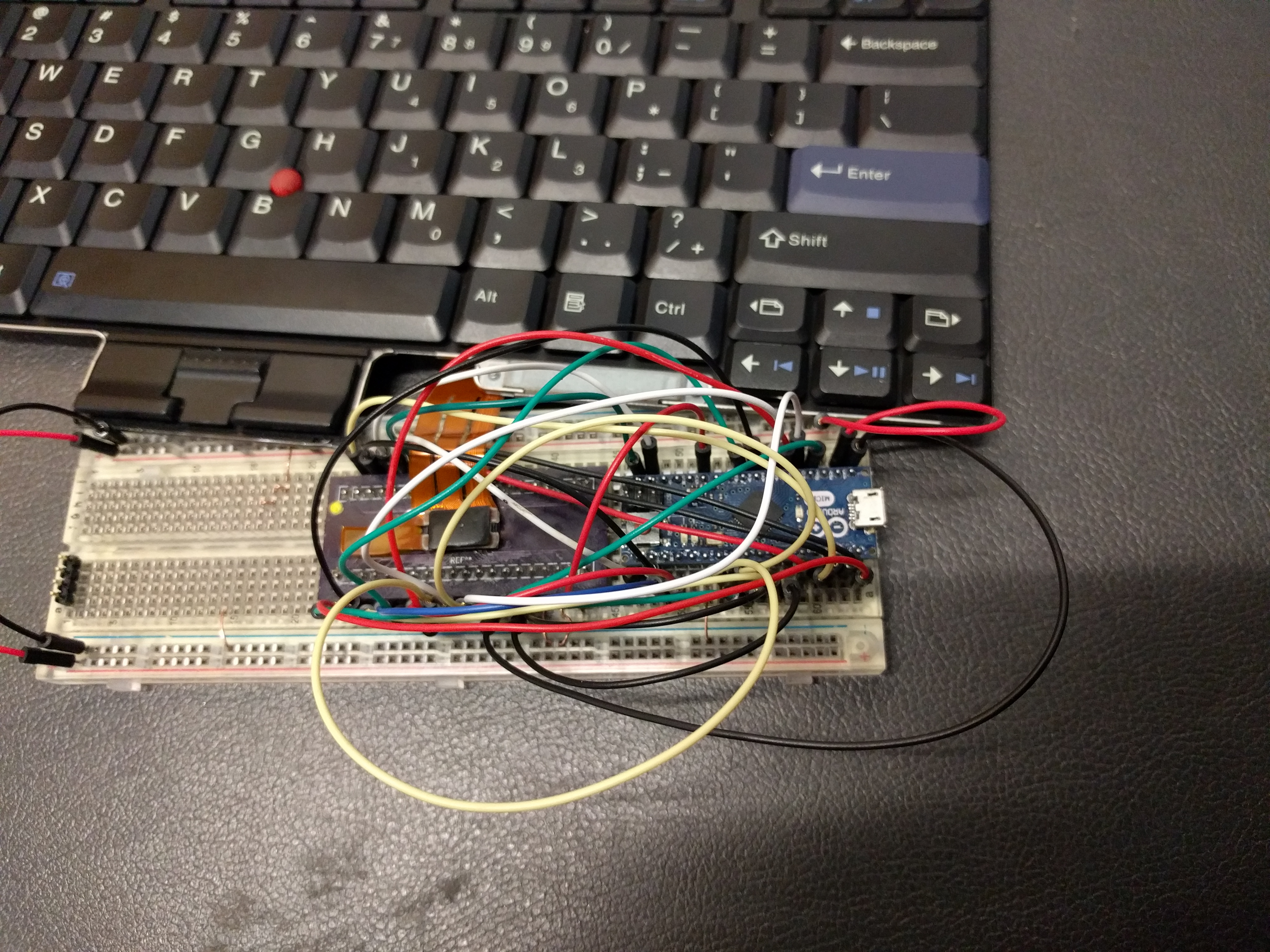
It actually worked, the gods have answered.
At least, qwerty works. Backspace and '\' are switched, and a few other small keymapping issues.
After the easy remapping fixes, there are a few larger remaining problems:
- Super and menu are left alt and right alt respectively, even if alt is not defined anywhere in the keymap.
- Even setting every no-op in the matrix, the alt keys do nothing.
- Fn sends several key presses, even though the pinouts say fn should have it's own pin, pin 1 the same way power does.
make -f Makefile.lufa clean && make -f Makefile.lufa
avrdude -v -c avr109 -p m32u4 -P /dev/ttyACM2 -U flash:w:t61_lufa.hex
Next steps:
- Pick an avr chip with more IO, do a custom board for it.
- Figure out what's up with the matrix that makes alt wrong, and super/page always alt.
- Test trackpad, shouldn't be hard there is example code.
- fix the fn key, and start using TMK keymap layers.
- num lock layer.